The Diffraction Limit
I have never fully understood the diffraction limit in microscopy and I thought it would be a good idea to learn the basic principles behind this concept before my research qualifying exam tomorrow. I am going to try to explain it succinctly here in a utilitarian way.
The diffraction limit describes the smallest feature size that an optical imaging system can resolve. The diffraction limit is driven by the physics of light; it is NOT based on manufacturing limitations we encounter when building microscopes or telescopes. In other words, the diffraction limit cannot be overcome with better glass grinding techniques or larger aperture objectives; it is a barrier imposed by physics [1], [4].
Mathematically, we can write the diffraction limit as the following equation [2]:
Where lambda is the wavelength of the light used to image the specimen and NA is the numerical aperture of the objective [2],[3]. For my bright field microscope objectives at 25X and 40X, I estimate that my diffraction limits are about 0.74 um and 0.49 um respectively. But where does this equation come from?
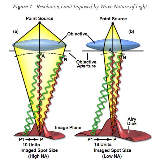
If we consider a bright field microscope, light from the source passes through the sample and then goes through an objective’s aperture. As the light passes through the edges of the aperture, it diffractsthe light. Diffraction is a bending of the light waves and it creates patterns of maxima and minima of the light waves [5]. These bending light waves create spots on the image plane of the microscope. Each spot is characterized as a central bright peak, surrounded by dark rings (minima) and bright rings (maxima) which are formed because the light has been diffracted [1]. The central spot is called the zeroeth order spot, and each successive bright ring is the first order, second order, third order ring, and so on [1]. We can call these spots with these special patterns “Airy disks” [1]. The size of the central spot in an Airy disk is controlled by the objective’s aperture angle and the wavelength of light being used [1]. Larger objective apertures result in smaller spot sizes [1].
Figure 1: Airy disks. Source: [1].
Let’s imagine the image plane is filled with these Airy disks (see Figure 1 for a visualization of a disk). The diffraction limit describes the smallest distance between two Airy disks that can be resolved by the microscope [1]. In other words, how close can two Airy disks get before we cannot tell them apart in the image? Different scientists have come up with different criterion for the diffraction limit. Rayleigh said that the diffraction limit is defined as the distance between two Airy disk peaks when the peak of one disk overlaps with the first minima of the other disk [1]. This is quite a conservative criterion; the Sparrow criterion is a little looser as it defines the diffraction limit as the distance between two Airy disks when the brightness between their central spots is uniform [1].
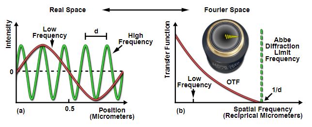
Figure 2: Abbe diffraction limit in space and frequency domains. Source: [1].
But the Abbe resolution is the definition that I presented at the top of the post, and the one that is most commonly accepted among scientists (I think). Abbe takes a different approach to this problem. Instead of thinking about the image as a collection of Airy disks, he thinks about it in the frequency domain. That is, he argues that we can represent every object, every feature in the image as a collection of sinusoids [1]. If you’ve been reading my posts on classical control theory, you know that we call this representation a Fourier series. Lower frequency sinusoids represent coarser features with longer wavelengths; these appear at the center of the objective’s aperture. Higher frequency sinusoids represent finer features with shorter wavelengths, and they appear at the edges of the objective’s aperture [1]. (See Figure 2 for an illustration of this.) The Abbe diffraction limit is the highest frequency wave that we can resolve in our image [1]. The frequency corresponds to a wavelength, which is the resolution of the image [1]. Any feature with frequencies above this limit cannot be detected by the microscope [1].
References
[1] Silfies, J, Schwartz, S, Davidson, M. “The Diffraction Barrier in Optical Microscopy.” Microscopy U. Nikon. https://www.microscopyu.com/techniques/super-resolution/the-diffraction-barrier-in-optical-microscopy Visited 09/03/2019.
[2] “Diffraction Limited System.” Wikipedia. https://en.wikipedia.org/wiki/Diffraction-limited_system Visited 09/03/2019.
[3] “Numerical aperture.” Wikipedia. https://en.wikipedia.org/wiki/Numerical_aperture Visited 01/08/2019.
[4] “The Diffraction Limits in Optical Microscopy.” AZoOptics. https://www.azooptics.com/Article.aspx?ArticleID=659 Visited 09/04/2019.
[5] “Diffraction.” Wikipedia. https://en.wikipedia.org/wiki/Diffraction Visited 09/04/2019.


