Example 11.1 (Nise)
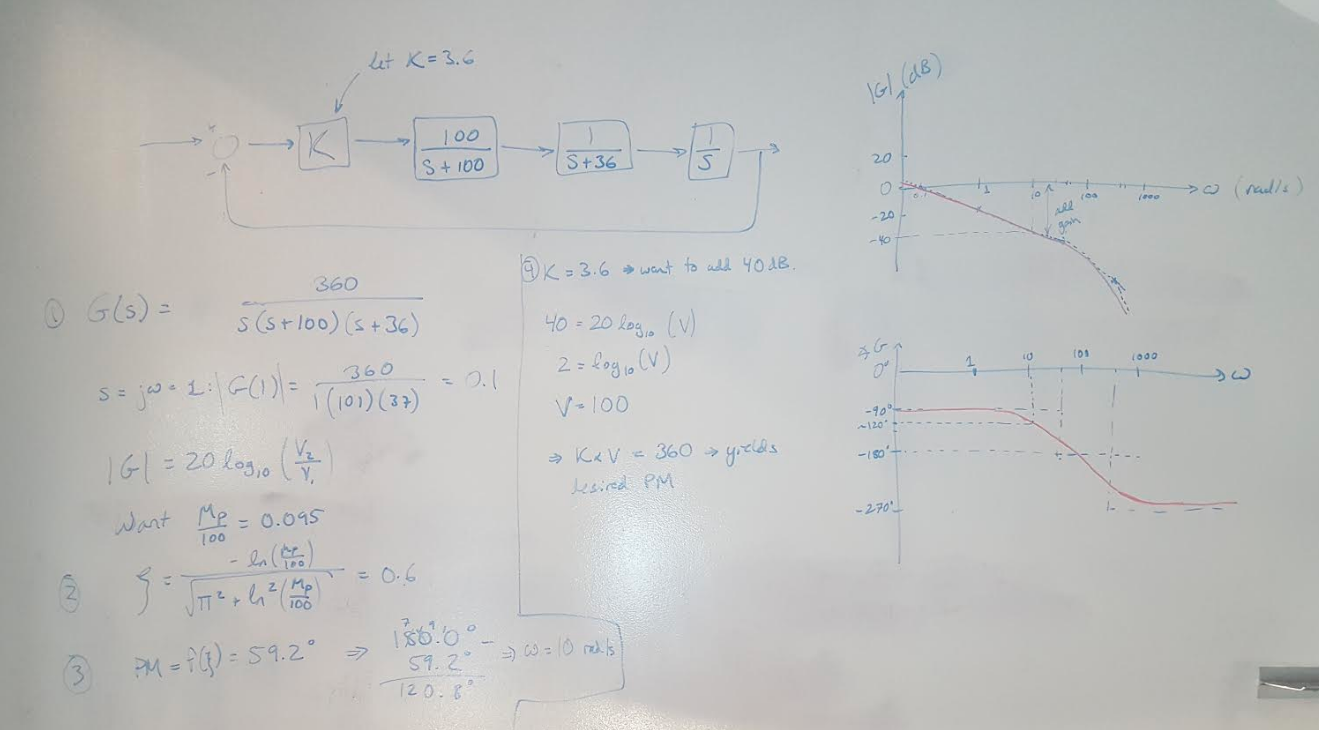
In this post I am going to design a proportional controller to meet a set of specifications using the Bode plot of the plant. This is presented as Example 11.1 in Nise [1]. The question asks for the gain required to yield a 9.5% overshoot in the transient response, and requires the solution to be presented in the frequency domain [1]. Here’s the flow of the answer [1]:
(1) Draw out the block diagram of the system and pick some nominal gain to start designing. (A good trick is to pick the gain so that the numerator is equal to the factored out coefficients of the denominator, or offset by an order of magnitude. In this case, the gain is set to 3.6 so that the numerator and denominator are a factor of 10 away from each other.) Draw the Bode plot for the uncompensated system.
(2) Calculate the desired damping coefficient for the given percent overshoot. We find that the coefficient is about 0.6 in this example.
(3) Calculate the phase margin required to meet the damping coefficient specification.
(4) Check the current phase margin on the uncompensated system. Now find the frequency that corresponds to the desired phase margin. In this case, we want a phase margin of about 60 degrees and the Bode plot tells us that this phase margin occurs at a frequency of 10 rad/s.
(5) Look at the magnitude plot. How much additional gain do you need to add to the system to move the crossover frequency to 10 rad/s? I find that I need to add about 40dB, or a gain of 100, to my current system. This means that my new compensator gain needs to be 3.6 * 100 = 360.
Next time I will go through more complex examples of designing lead and lag compensators. But before then we are going to take a quick detour into the fundamentals of Nyquist plots because I am still finding them quite challenging.
 Figure 1
References:
[1] Nise, Norman S. Control Systems Engineering, 4th Ed. John Wiley & Sons, Inc. 2004.
