Example 11.3 (Nise)
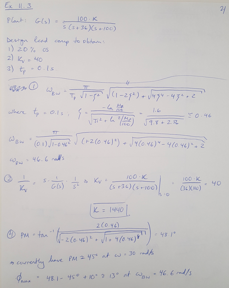
In this post I am going to walk through the lead compensator design process using Bode plots. This question is drawn from Nise’s Example 11.3 [1]. The objective of this question is to design a lead compensator for the plant shown below. The design requirements are:
(1) 20% overshoot
(2) Steady state velocity error constant = 40
(3) Peak time of 0.1 seconds
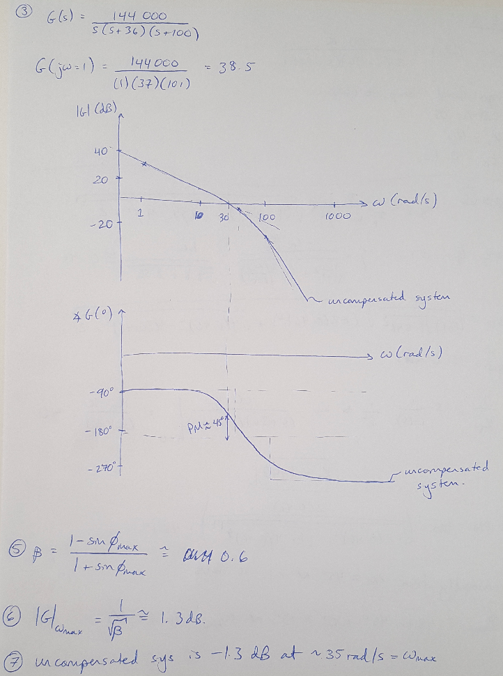
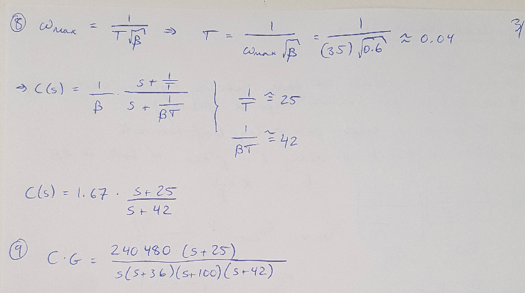
The design process is shown below.

Figure 1

Figure 2

Figure 3
References:
[1] Nise, Norman S. Control Systems Engineering, 4th Ed. John Wiley & Sons, Inc. 2004.
Written on October 7, 2019
