Example 9.1 (Nise)
In this next series of posts, I am going to do a couple of examples from Nise [1] to practice designing different kinds of controllers. Some of these have been solved fully in the textbook, and others are provided as practice problems, so if you cannot read my solutions, please look in the textbook for more clarity. I should note that all my images today were taken from the whiteboard, instead of my customary paper-based figures, because I am also trying to practice good board management for the actual qualifying exam.
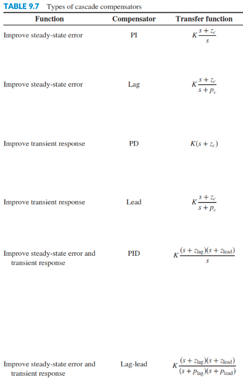
This first problem practices designing PI controllers, which are good for improving the steady state response of a system. Please refer to my older posts on controller and compensator design for more details of the theory behind the different kinds of controllers. I have also included a table below from [1] which does a nice job of summarizing the different kinds of controllers and when they should be used. Today I will probably do posts for PI, lag, and PD controllers. Next time I will focus on lead, PID and lead-lag controllers.

Figure 1
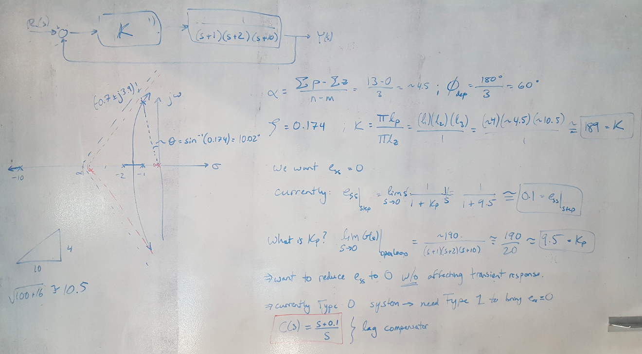
Example 9.1: Designing an Ideal PI Controller [1]
The objective of this problem is to make the steady state error (in response to a step input) zero. I know that the system has a damping coefficient of 0.174. The problem solution flows as follows:
(1) Solve for the gain that positions the closed loop poles such that the damping coefficient of the system is indeed 0.174. (We can approximate this system as second order because the third root is very fast and far from the dominant complex pair of poles.)
(2) Solve for the steady state error gain, Kp.
(3) Solve for the uncompensated steady state error.
(4) Choose a PI controller with a zero. This is kind of a hybrid PI - lag controller since purely integral control does not have a derivative component by definition but pure lag compensators do not have integrators. We put the zero close to the origin so that it does not shift the root locus significantly (we don’t want to change any aspect of the system’s performance except for the steady state error).
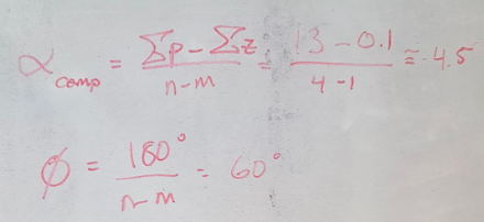
(5) Show that the root locus does not change very much by recalculating the location and angle of the asymptotes of the root locus. Therefore we can use the same closed loop gain, K, to recalculate Kp and show that the steady state error is now 0.

Figure 2

Figure 3
References:
[1] Nise, Norman S. Control Systems Engineering, 4th Ed. John Wiley & Sons, Inc. 2004.
