Drawing Nyquist Plots
Recently I wrote a post on stability of linear systems where I introduced the Nyquist plot. Now I want to go into the details of how to draw one without using a Bode plot. If I have time in the future I will also explain how to draw a Nyquist plot using the Bode plot - it is an easier method, in my opinion, but it assumes that you have a reliable Bode plot to start with.
I first want to clarify something from last post: The Caucy Argument Principle states that [3]:
The net number of clockwise encirclements, N, equals the number of zeros (closed-loop system roots) in the RHP, Z, minus the number of open-loop poles in the RHP, P: N = Z - P
I learned to draw Nyquist plots this way from Brian Douglas [1], but he references a lecture by Prof. Gopal [2], so I will cite both here for completeness. We will use an example transfer function given below, but first I want to go over two concepts that will be useful in this example. The first concept is the idea that Nyquist plots are symmetric about the real axis (in both the s- and w-planes) [1]. We will use this to reduce the amount of work we have to do to obtain the plot.
The second concept is the idea that the part of the Nyquist contour in the s-plane that is at infinity (i.e. the curved part that encircles the entire RHP) maps to a single point in the w-plane if the transfer function is proper or strictly proper [1]. This is because, if we imagine ourselves sitting on this part of the contour, the poles and zeros of the transfer function would appear grouped at a point near the origin [1]. That is, no matter where we are at infinity, we would be so far away that we could not see the contributions of the poles and zeros to the phase. So we only need one point to represent the phase anywhere at infinity on the RHP. If the system is strictly proper, this point is the origin; if the system is proper, this point is somewhere on the real axis [1]. This also means that I really only care about what is happening along the imaginary axis in the s-plane [1].
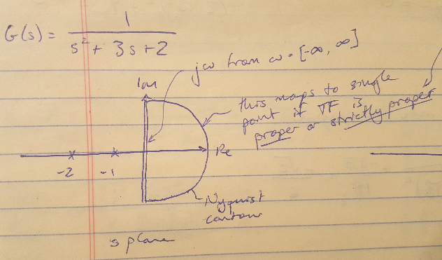
Figure 1
Now let’s dive into the example. The open loop transfer function is given below [1]. It has no zeros (Z = 0) and two poles in the LHP (P = 0). So we are expecting that N = Z - P = 0 for this example.

Prof. Gopal’s method states that you only need 4 points to be able to sketch the Nyquist plot, and these points are [1],[2]:
(1) w = 0
(2) w = infinity
(3) The intercept of the Nyquist plot (in the w-plane) on the imaginary axis
(4) The intercept of the Nyquist plot (in the w-plane) on the real axis
In order to get all of these points, we first need to substitute s = jw into the system transfer function [1]. Why don’t I substitute s = sigma + jw into the transfer function, why am I omitting the real part? I omit the real part for the reason we just discussed - as soon as I move onto the positive real axis at a distance of infinity from the origin, the phase contribution from the transfer function basically looks like zero to me. It’s not important to me. So I can omit considerations of the real component of the transfer function completely from this procedure.

Instead, let’s substitute j*w into my transfer function as shown below.
Now let’s see what happens when w = 0 - I find that the transfer function is equal to 0.5, so I plot that on the positive real axis of the w-plane. Similarly, I can see that when w = infinity, my transfer function is equal to 0, so I can also plot that on the w-plane.
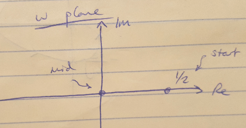
Figure 2
Next we need to find the imaginary and real axis intercepts of the Nyquist plot. To do this, I am going to rationalize the denominator of my transfer function and then separate the real and imaginary components as shown below.

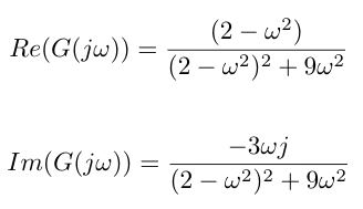
I can solve for the intercept for the imaginary axis by setting the real axis component equal to zero and solving for w. Then I plug this value of w into the imaginary component to get the imaginary axis intercept. This math is shown below, and the final Nyquist plot is also given. Notice that I always draw my Nyqyuist contour in the s-plane in the clockwise direction, so the point in the w-plane that corresponds to the origin in the s-plane is the starting point for my contour, and I move in the direction of the point corresponding to w = infinity in the s-plane [1].
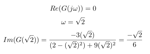
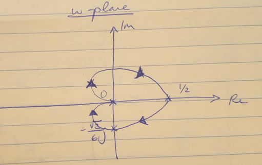
Figure 3
This plot shows that my system is stable because I have no encirclements of -1 and N = Z - P = 0 as we expected.
References
[1] Douglas, Brian. “Nyquist Stability Criterion, Part 2.” https://www.youtube.com/watch?v=tsgOstfoNhk&list=PLUMWjy5jgHK1NC52DXXrriwihVrYZKqjk&index=27 Visited 09/16/2019.
[2] Gopal, Madan. “Lec-36 The Nyquist Stability Criterion and Stability Margins (Contd.).” https://www.youtube.com/watch?v=Rbvau5oXOkg Visited 09/16/2019.
[3] Franklin, G., Powell, J.D., Emami-Naeini, A. Feedback Control of Dynamic Systems, 6th ed. Pearson. 2009.
