Steady State Error
In this post I want to talk about the Final Value Theorem and steady state error because these concepts will be useful as we go on to discuss controller design in more detail. Steady state error describes how far the system deviates from the desired reference signal as time goes to infinity [1]. It is a commonly used performance metric for controller design, which is why I want to establish the concept now before we apply it in future posts on controller design [2]. I will start the discussion, though, with the Final Value Theorem because that concept is critical to understanding steady state error.
The Final Value Theorem is used to find the “final value” of a system as time goes to infinity. It is derived from the Laplace transform of the derivative, taken as time goes to infinity (or s goes to zero), as shown in the equation below [2]. Note that we can only use the Final Value Theorem if a system is stable, or at least has all its poles at the origin (and the left half plane). If the system is unstable or a non-decaying sinusoid, then the Final Value Theorem will produce results, but they will be meaningless because the system does not actually converge to zero [1],[2]. Don’t be fooled - always test for stability before using the Final Value Theorem!
Now that we have the Final Value Theorem equation, we can use it to find the steady state error. The formal definition of steady state error, according to Nise, is the difference between a reference signal and the corresponding output signal for a prescribed test input as time goes to infinity [2]. I italicized “for a prescribed test input” because this helps to understand the process we are going to use. We are going to take the transfer function of the error of a system and apply a test input to that transfer function. The test input can be a step input (corresponds to a position command), a ramp input (corresponds to a velocity command) or a parabolic input (corresponds to an acceleration command) [1], [2]. The error transfer function will describe how the system error responds to that input, and we can use the Final Value Theorem to see how the error will respond in the long-term. This is shown in Equation 2 below.
Note that for unity feedback, you can also write the error as the ratio between the reference signal and the forward transfer function, G(s) [2]. This is shown in Equation 3 below. This form will be helpful in the next step of our discussion.
If we substitute the test input for R(s) and solve the Final Value Theorem for our system, we can get 3 possible types of steady state errors:
(1) Zero error: this means that the system is capable of eliminating all steady state error. In order to do this the system must have at least one pole at the origin (an integrator). (2) Finite error: this means that the system is capable of reaching steady state given this input, but it does not have enough integrators to eliminate all of the error produced by following the test signal. (3) Infinite error: this means that the system cannot track this reference signal at all.
The results of the steady state error equation can also be used to help us determine the system “Type”. The system type is a number corresponding to the number of integrators it possesses [1]. For example, if a system is Type 0, it does not have any integrators. It can only track a step input, but even with that input it will have some finite steady state error because it has no integrators with which to eliminate that error. Conversely, a Type 1 system has 1 integrator and it can track a step input with zero error and a ramp input with finite error [1], [2].
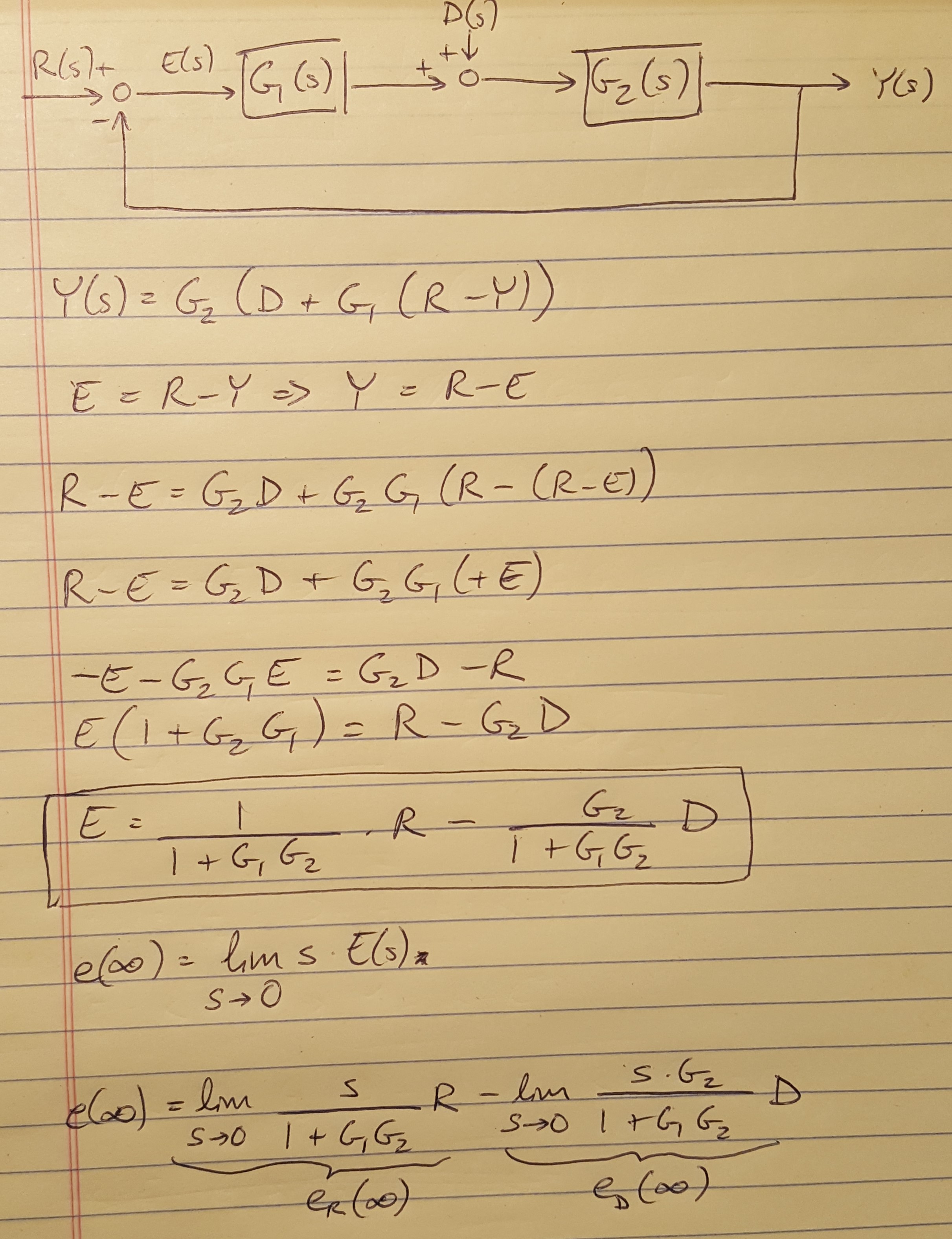
What if you want to find the steady state error contribution from a disturbance input? I have shown the block diagram for a disturbance input and the derivation of the equation for steady state error in the figure below. Notice that I went back to the fundamentals shown in Equation 1 to get the equation for steady state error as a function of contributions from both the reference signal and the disturbance signal.

Figure 1
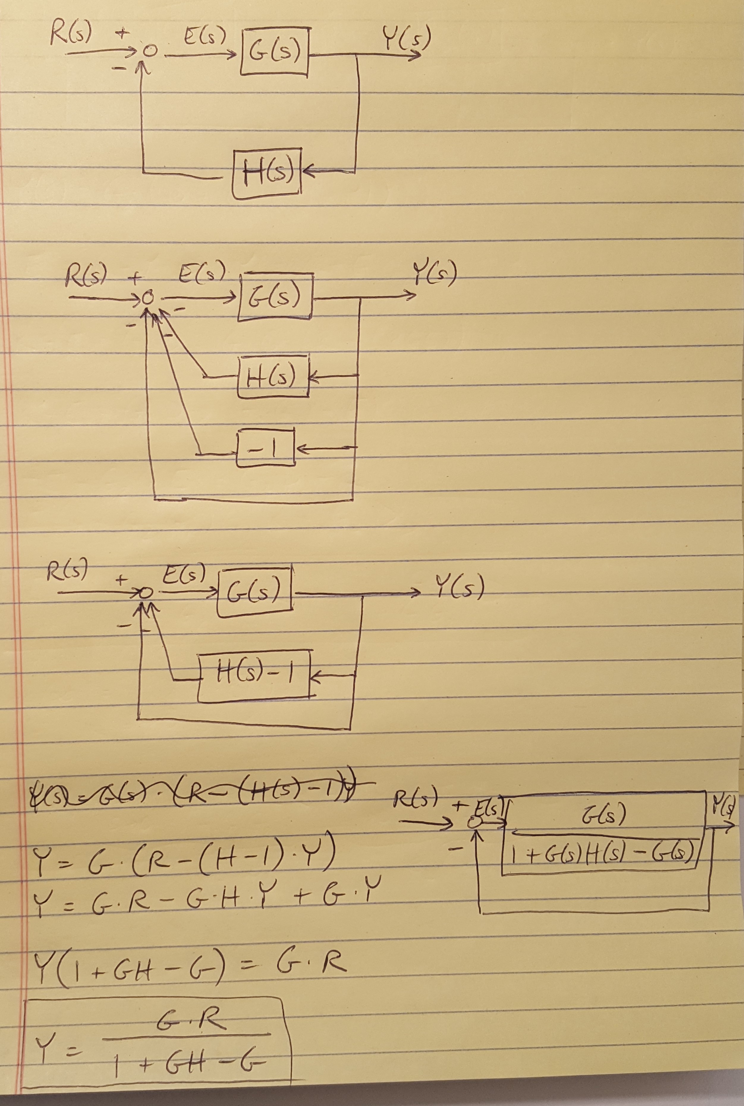
We also made an important assumption in our discussion up to this point: we assumed that we had unity feedback because it simplified the math. However, we often have non-unity feedback because sensor noise and system dynamics can contribute to the feedback path of our system. In these cases, it is helpful to apply the trick demonstrated below to re-draw the block diagram as a unity feedback system. I have worked out some of the math alongside the diagrams.

Figure 2
Now that we have this concept in hand, next time we will work through an example of the design process to meet steady state and transient performance requirements using root locus plots.
References
[1] Douglas, Brian. “Final Value Theorem and Steady State Error.” https://www.youtube.com/watch?v=PXxveGoNRUw&list=PLUMWjy5jgHK1NC52DXXrriwihVrYZKqjk&index=15 Viewed on 07/23/2019.
[2] Nise, Norman S. Control Systems Engineering, 4th Ed. John Wiley & Sons, Inc. 2004.


