Example 9.2 (Nise)
This is the second post in a series where I am solving examples of controller design problems from Nise [1]. This example is focused on designing a true lag compensator. The useful piece of this problem is using the gain ratio (of compensated : uncompensated gain) to choose the pole and zero locations.
Example 9.2: Designing a Lag Compensator [1]
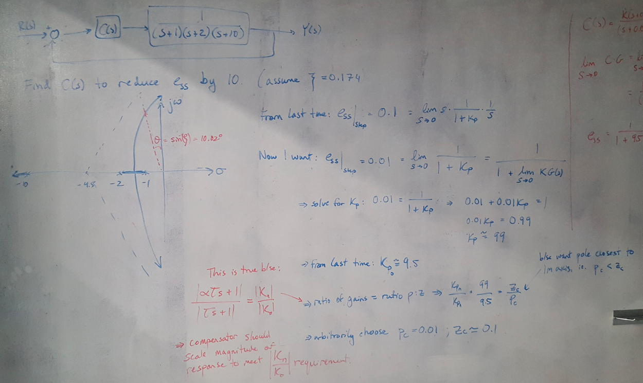
This problem gives you a plant and asks you to design a lag compensator that reduces the steady state error by a factor of 10. The flow of the solution is:
(1) Calculate the uncompensated steady state error (we use some information from Example 9.1 to help with this calculation, since the system is the same).
(2) Divide the steady state error by 10 and solve for the new Kp required to meet this objective.
(3) Use the gain ratio (Kp_new : Kp_old) to write the pole-zero ratio for the lag compensator. Note that for lag compensators, the integrator’s (i.e. the pole’s) behavior should dominate the system so we want to put the pole closer to the Imaginary axis than the zero. This means that z > p.
(4) Arbitrarily choose the pole location to be somewhere very close to the origin, and solve for the zero’s location.
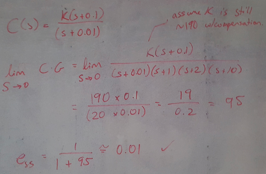
(5) Solve for the steady state error of the compensated system (assume that the gain is still about the same with compensation, since the compensator is very close to the origin and does not shift the root locus signficantly). Show that you have met the design requirements.
 Figure 1
 Figure 2
References:
[1] Nise, Norman S. Control Systems Engineering, 4th Ed. John Wiley & Sons, Inc. 2004.
