Fundamentals of Lead and Lag Compensators
This is now my third post on designing lead and lag compensators (I wrote a post on lead compensators, and a summary of lead, lag and lead-lag compensators. I am finding controller design to be the most challenging concept that I have encountered so far in studying classical control theory. I just did my first mock qualifying exam this morning and this was the part of the exam that tripped me up. So, I’m going to write one post here that summarizes the basic concepts as clearly and succinctly as possible. Then I will post a couple of design examples to walk through the process of designing controllers.
First I just want to clarify one thing that will help me remember the difference between lead and lag compensators: lead compensators are like PD controllers, so the zero (the derivative component) dominates the system. Therefore the zero is closer to the imaginary axis. Likewise, lag compensators are like PI controllers, so the pole dominates the system. Therefore the pole is closer to the imaginary axis. If I can just remember that, we’ll be off to the races. Now let’s start at the beginning.

Lead Compensators
Lead compensators add 90 degrees of phase to a system [1]. This is equivalent to performing a differentiation operation [1]. Think about it - if you add 90 degrees to a sine wave, you get a cosine wave. And the derivative of a sine wave is also a cosine wave. Kind of cool, right? I also like to remember that lead compensators are better for improving the transient response of a system [3].
The equation for lead and lag compensators are the same, but let’s start by considering the equation as it would be written for a lead compensator. The equation is shown below in two different forms [1]. The left hand equation is probably easier to work with when designing in Bode plots (because the breakpoint frequencies are simply the omega values) whereas the right hand equation is easier to use with the root locus because the poles and zeros are listed explicitly.

Remember at the top of the post that I said lead compensators are like PD controllers so the zero dominates? That means that for lead compensators, the zero’s frequency is SMALLER than the pole’s frequency. This places the zero closer to the Imaginary axis, where it is slower and will dominate the system response.
The Bode plot for the lead compensator is shown below, as well as the root locus for the compensator [1]. We can pull some useful information out from the Bode plots as well, which helps us to design the compensator to meet a specific set of requirements [2]. The magnitude plot shows us the gain of the compensator at the maximum phase of the compensator [2]. The phase plot shows us the maximum phase, as well as the corner frequencies and the frequency corresponding to the maximum phase [2]. This will be useful in the future.
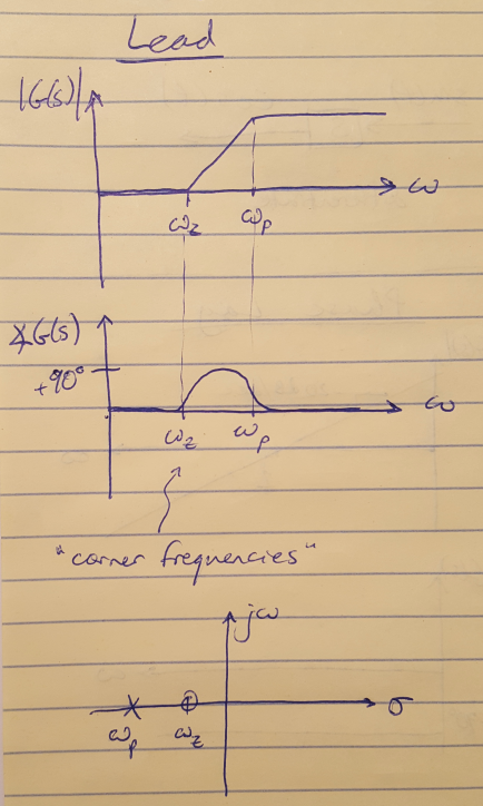
Figure 1
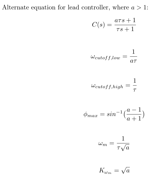
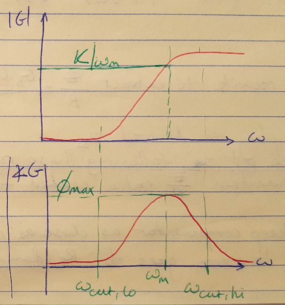
Figure 2
Lag Compensators
The math and the concepts for lag compensators are pretty similar, only now we are subtracting 90 degrees of phase [1]. This is equivalent to performing an integration operation [1]. Lag compensators are usually used to improve the steady state response of a system [3]. Since lag compensators are like PI controllers, the pole is the dominant feature of the compensator so the pole frequency is smaller than the zero frequency. This moves the pole closer to the Imaginary axis.
The Bode plot and root locus for a typical lag controller are shown below [1]. Notice that they are just the inversion of the plots for the lead controller.
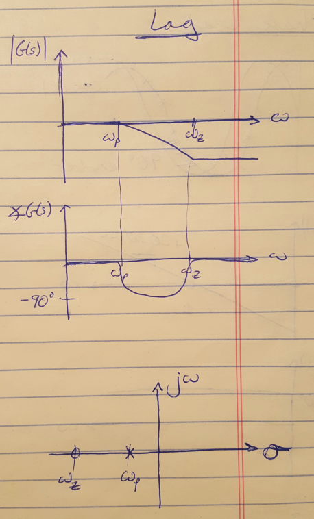
Figure 3
Lead-Lag Compensators
We can also combine the two types of compensators listed above to yield a lead-lag compensator. We would use a lead-lag compensator (the equivalent of a PID controller) for improving both the transient and the steady state responses of a system [3]. The Bode plot and root locus plot for lead-lag compensators are shown below [1].
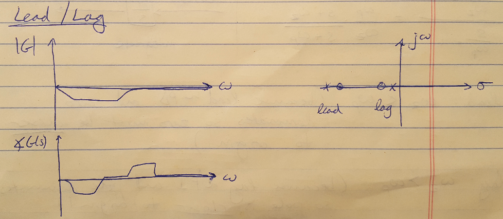
Figure 4
Now that we have covered the basics, next time I am going to start solving some simple examples so that we can start to see the design process in action.
References
[1] Douglas, Brian. “What are Lead Lag Compensators? An Introduction.” https://www.youtube.com/watch?v=xLhvil5sDcU&list=PLUMWjy5jgHK1NC52DXXrriwihVrYZKqjk&index=33 Visited 09/18/2019.
[2] Douglas, Brian. “Designing a Lead Compensator with Bode Plot.” https://www.youtube.com/watch?v=rH44ttR3G4Q&list=PLUMWjy5jgHK1NC52DXXrriwihVrYZKqjk&index=35 Visited 09/18/2019.
[3] Nise, Norman S. Control Systems Engineering, 4th Ed. John Wiley & Sons, Inc. 2004.
